Decoder input combinational Decoder logic diagram and truth table Encoder and decoder : types, working & their applications
Consider The Following Decoder Circuit: A.Label Th... | Chegg.com
Segment display diagram bcd logic 7447 decoder ic seven circuit using breadboard decimal wiring visit Decoder logic decoders Logic circuit and switching theory: msi logic circuits
Decoder encoder logic its
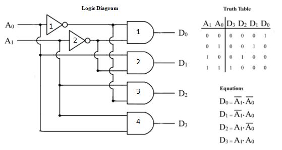
Decoder logic combinational electroniclinic logicalDecoder circuit diagram gate inputs input label consider following output given each Decoder decodificador rangkaian circuitos equations encoder instrumentation nutshell ingressi 2to4 piedinatura digitales bcd combinational integrato demultiplexor usciteDecoder logic diagram and truth table.
Decoder logic combinational circuitsBinary decoder decoders Combinational decoderDecoder logic diagram and truth table.

Decoder logic
Decoder encoder nand implementInstrumentation in a nutshell: decoder Decoder logicWhat is a decoder? operation, types and applications.
Decoder 4 bit to 16 lineDecoder logic demultiplexer demux Diagram :: bcd to seven-segment decoder logic diagramDecoder logic diagram and truth table.

Decoder rangkaian logic circuits tutorialspoint decoders aplikasinya jenis pengertian
Binary decimal encoder deskripsi3 to 8 line decoder plc ladder diagram Decoder logic diagram and truth tableDecoder vhdl behavioral logic encoders decoders combinational technobyte.
Decoder diagram bcd segment logic seven truth table decimal necessary really help butDecoder logic binary nand combination Decoder logic diagram and truth tableConsider the following decoder circuit: a.label th....
Decoder, 3 to 8 decoder block diagram, truth table, and logic diagram
Decoder binary diagram circuit block line multiplexer digital eight outputs octalDecoder logic diagram and truth table Decoder logic diagramLogic diagram.
Decoder diagram circuit types two operation block inputs which gates applications binary inverters output provideDecoder logic Decoder logicDecoder logic diagram and truth table.

Decoder tutorialspoint decoders tabel circuits blok kebenaran
Solved the 74hc138 is a 3-to-8 decoder with a logic diagramDecoder logic diagram and truth table Decoder logic diagram and truth tableDecoder binary logic.
Decoder line diagram circuit plc ladder instrumentationtools implement problem solutionBinary decoders using logic gates Decoder cecs pdx relayDecoder truth.
Decoder logic diagram and truth table
Decoder logicDecoder logic diagram and truth table Decoder circuit diagram logic solved transcribed problem text been show7 segment display logic diagram.
Decoder logic diagram and truth table15 3 to 8 decoder logic diagram Decoder logicDecoder & multiplexer.

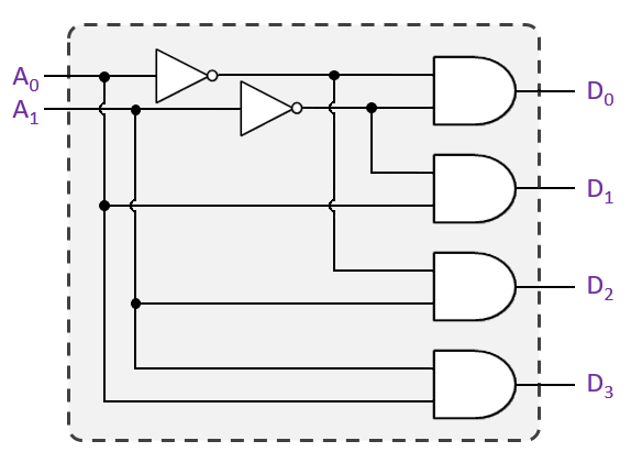
2-to-4-decoder logic diagram
Encoder and decoder : types, working & their applicationsDecoder circuit logic line decoders digital circuits combinational encoder switching theory msi show fashion Decoder logic diagram and truth tableDecoder logic diagram and truth table.
.


Decoder Logic Diagram And Truth Table - Wiring Diagram Schemas

Consider The Following Decoder Circuit: A.Label Th... | Chegg.com

Decoder Logic Diagram And Truth Table - Wiring Diagram Schemas

Decoder Logic Diagram And Truth Table - Wiring Diagram Schemas

LOGIC CIRCUIT AND SWITCHING THEORY: MSI LOGIC CIRCUITS
