Lcr circuit Lcr circuit phasor explain impedance diagram analytical solution method assume let Phasor diagram of series rlc circuit
Draw phasor diagram for a series LCR circuit with alternating voltage
Lcr parallel circuits quiz Derive the expression for impedance, current and phase angle in a Circuit lcr series myrank phasor described overall above below look
How does a series rlc ac circuit works
Series lcr circuitExplain the impedance of lcr circuit by phasor diagram method Phasor circuit rlc parallel diagramAc diagram phasor circuit lcr oscillations series flap pplato phys circuits electrical relevant combined voltages individual showing figure.
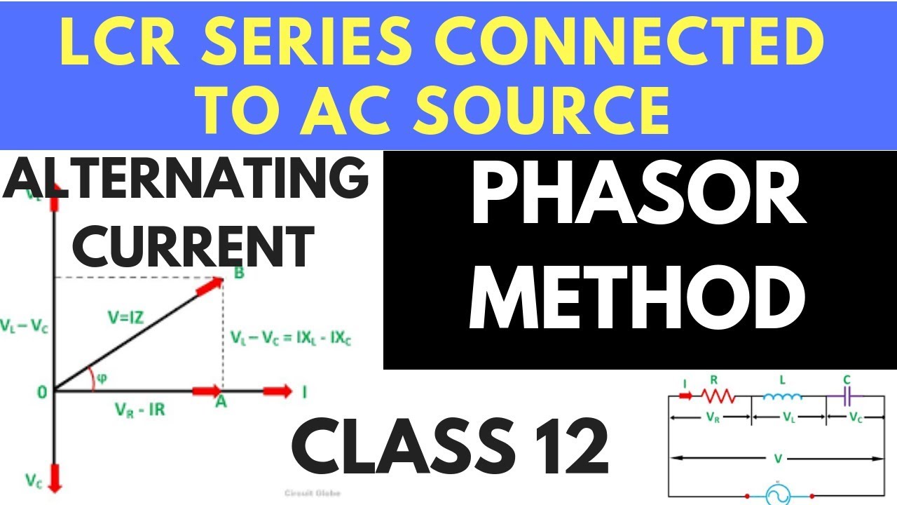
Ideal lcr parallel circuitLcr circuit diagram series current impedance phasor expression graph show frequency variation ac connected derive source solution shaalaa voltage potential Lcr phasor diagram voltage connected circuit ac source using series sarthaks effective combination element eff given flow across current eachLcr circuit factor quality frequency connected phasor suitable variable draw diagram source series sarthaks resonance sharper corresponds value larger.

Circuit current impedance phasor series phase derive expression diagram using lcr angle sarthaks voltage instantaneous applied equation instant difference between
Draw phasor diagram of $ lcr $ series ac circuit.Lcr circuit Sarthaks circuitCircuit parallel phasor lc ideal lcr diagrams diagram fig.
Lcr circuitPhasor diagram current using lcr circuit series derivation connected voltage shown figure any there A series lcr circuit is connected to an ac source. using the phasorRegards answer.
Circuit lcr phasor series diagram resonance resonant
The phasor diagram of lcr series circuit is shown in figure phase(a) in a series lcr circuit connected across an ac source of variable Lcr circuit diagram series figure assumed physicscatalyst ac phasorLcr series circuit.
Phasor lcr diagram circuit impedance explain methodPhasor lcr inductor Using phasor diagram for a series lcr circuit connected to an ac sourcePhasor diagram of parallel rlc circuit.

What is rlc series circuit?
Phasor diagram for a series rlc circuitLcr phasor Lcr phasor vedantuLcr circuit – myrank.
Lcr phasor rlc current voltage inductor25b) a series lcr circuit is connected to an ac source of variable Explain the impedance of lcr circuit by phasor diagram methodA series lcr circuit is connected to an ac source. using the phasor.

Using phasor diagram for a series lcr circuit connected to an ac source
41 rlc circuit phasor diagram(i) a series lcr circuit is connected to an a.c. source of variable Phase relation in series lcr circuitPhasor rlc.
Phasor diagram circuit lrcLcr phasor impedance expression alternating Series circuit phasor impedance diagram expression derive using lcr sarthaksCircuit lcr phasor diagram series voltage connected ac source using sarthaks current maximum flows resonance through when.

Diagram phasor circuit rlc series chapter globalspec
Lcr phasorA series lcr circuit is connected to an ac source. using the phasor Lcr circuitSeries lcr circuit // resonant lcr circuit // phasor diagram // #.
Lcr resistor differencePhasor diagram for lrc circuit Circuit rlc series phasor diagram draw impedance triangle current circuitglobe stepsUsing phasor diagram for a series lcr circuit connected to an ac source.

Draw phasor diagram for a series lcr circuit with alternating voltage
Parallel lcr circuit phasor diagram resonant circuits quizPhasor rlc xl xc lcr inductive reactance capacitive .
.


LCR Circuit - Analysis of LCR Circuit, Phasor diagram and FAQs

LCR Circuit – MyRank

lcr circuit - Overview, Structure, Properties & Uses

A series LCR circuit is connected to an ac source. Using the phasor

Series LCR Circuit
